Sending audio to LKV373 HDMI extenders
My current flatmate has a bunch of these HDMI extender devices (also apparently known as “LKV373” / “Lenkeng extenders” / “LK-3080-ACL”). They’re pretty nifty: HDMI goes in one end, they emit UDP over ethernet, and then HDMI comes out on the receiver end with surprisingly minimal latency (around 100ms).
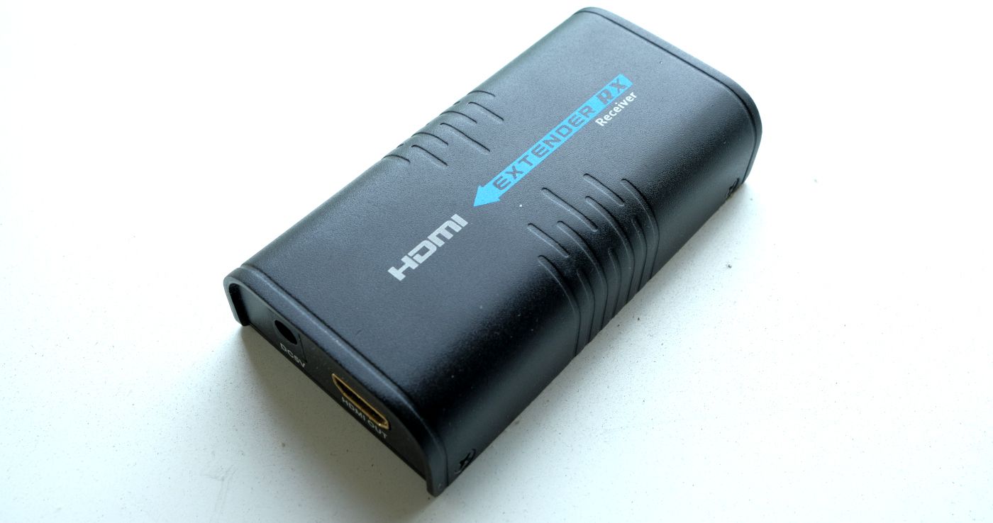
image: the receiver end of a transmitter-receiver pair, taken by said flatmate
A couple months ago we decided it’d be quite nifty to be able to play arbitrary audio out of the devices without having to plug a transmitter into someone’s laptop – so that we could have BBC Radio 4 or something constantly playing whenever the sound system is turned on.
My flatmate’s blog post, “Ludicrously cheap HDMI capture for Linux”, outlined a way to
decode the signal the transmitters sent (using his own tool,
de-ip-hdmi). But could we do the opposite,
and encode signals the receivers would accept?
Testing without the actual devices
I figured I’d start by looking at de-ip-hdmi’s source code to see how it
decoded the packets and then use it as a way to test the output of my
custom sender until it was able to decode what I was sending. It’s pretty
unlikely that I’d just be able to send audio without also sending a picture,
so I tried to figure out the picture format first.
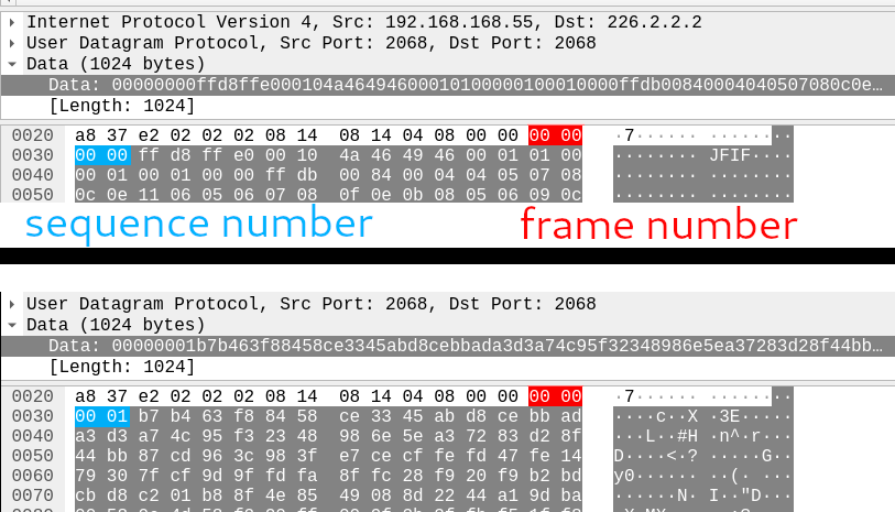
The video picture packets have a fairly simple format: two big-endian, 16-bit integers (frame number, and sequence number), and then data, up to 1020 bytes (making UDP packets with a 1024-byte payload, total).
Extracting the output from de-ip-hdmi with a transmitter running
confirms that the data is just a JPEG:
$ file test.mjpeg
test.mjpeg: JPEG image data, JFIF standard 1.01, aspect ratio, density 1x1, segment length 16, baseline, precision 8, 1920x1080, components 3
The frame number counts monotonically up from 0, incrementing with each new frame. Since you’re not going to fit a whole JPEG frame in 1020 bytes, the sequence number provides a way of splitting the frame up into multiple chunks; you increment it for each chunk you send within a frame, while keeping the frame number constant.
The de-ip-hdmi source code to decode
looks like this:
// taken from the de-ip-hdmi source code, in Go
FrameNumber := uint16(0)
CurrentChunk := uint16(0)

buf := bytes.NewBuffer(ApplicationData[:2])
buf2 := bytes.NewBuffer(ApplicationData[2:4])
binary.Read(buf, binary.BigEndian, &FrameNumber)
binary.Read(buf2, binary.BigEndian, &CurrentChunk)

// does stuff with ApplicationData[4:]
Seems simple enough. I wrote a small Rust struct that could chunk up a
slice of bytes into 1024-byte vectors that fit this format:
struct FrameChunker<'a> {
    inner: &'a [u8], // the data to send
    frame_no: u16, // frame number
    seq_no: u16 // sequence number
}

impl<'a> FrameChunker<'a> {
    // constructor emitted for brevity

    // get a new 1024 (or less)-byte chunk to send
    fn next_chunk(&mut self) -> Vec<u8> {
        let mut ret = Vec::with_capacity(1024);
        let (remaining, last) = if self.inner.len() > 1020 {
            (1020, false)
        }
        else {
            (self.inner.len(), true)
        };
        // this is from the `byteorder` crate's `WriteBytesExt` trait
        ret.write_u16::<BigEndian>(self.frame_no).unwrap();
        ret.write_u16::<BigEndian>(self.seq_no).unwrap();
        ret.extend(&self.inner[..remaining]);
        self.inner = &self.inner[remaining..];
        self.seq_no += 1;
        ret
    }

    // returns true if we're done transmitting the current frame;
    // used to know when to send the next one
    fn is_empty(&self) -> bool {
        self.inner.is_empty()
    }
}
I then made a little 1920×1080 all white JPEG in GIMP, wrote it to a file, and
wrote some code to send out UDP multicast packets in the format the receiver
(and de-ip-hdmi) would expect:
// The magic IPv4 address for the multicast group the transmitter would send
// to.
const MAGIC_ADDRESS: Ipv4Addr = Ipv4Addr::new(226, 2, 2, 2);

fn main() {
    // load the test image data in at compile-time
    let test_data = include_bytes!("../white.mjpeg");

    // make a UDP socket for sending
    // note: this requires creating an interface with this address
    let mjpeg = UdpSocket::bind("192.168.168.55:2068").unwrap();
    // destination address:port for video picture data
    let mjpeg_dest: SocketAddr = "226.2.2.2:2068".parse().unwrap();

    // join the multicast group
    mjpeg.join_multicast_v4(&MAGIC_ADDRESS, &"192.168.168.55".parse().unwrap()).unwrap();

    // current frame number
    let mut frame_no = 0;
    loop {
        let mut chonker = FrameChunker::new(frame_no, image);
        while !chonker.is_empty() {
            let buf = chonker.next_chunk();
            mjpeg.send_to(&buf, mjpeg_dest).unwrap();
        }
        frame_no += 1;

        ::std::thread::sleep_ms(33);
    }
}
I added a suitable network interface for the sender to use (the actual flat networking setup uses VLANs for the HDMI traffic, but I found out that if you just want to test then adding a loopback interface also works):
$ sudo ip link add link enp5s0f3u1u1 name showtime0 type vlan id 1024
$ sudo ip link set dev showtime0 address 00:0b:78:00:60:01
$ sudo ip addr add 192.168.168.55/32 dev showtime0
With much anticipation I then ran the code for the first time, with de-ip-hdmi
running in parallel – and got…nothing.
Adventures in bitshifting
Turns out I forgot something else in the packet format: a way to signal the
last chunk in a series of chunks for a frame. Going back to de-ip-hdmi:
if uint16(^(CurrentChunk >> 15)) == 65534 {
	// Flush the frame to output
	// [code snipped]

	CurrentPacket = Frame{}
	CurrentPacket.Data = make([]byte, 0)
	CurrentPacket.FrameID = 0
	CurrentPacket.LastChunk = 0
}
What the heck is uint16(^(CurrentChunk >> 15)) == 65534 doing? Let’s break
that down:
- it shifts
CurrentChunkto the right by 15 bits, discarding all bits apart from the most significant bit (MSB), which becomes the new least significant bit (LSB). - unary
^(caret) is the Go “logical NOT” operator, so we flip all of the bits in the result above 65534is a 16-bit integer with every bit set except the LSB
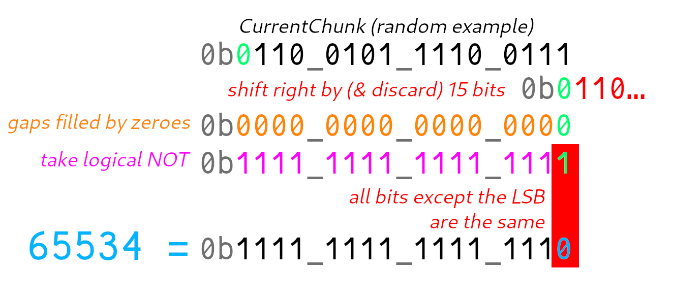
So… this is a very long-winded
way of checking whether the MSB of
CurrentChunk is equal to 1 (in Rust, (number & 0b1000_0000_0000_0000) > 0).
Accordingly, we need to set the MSB to 1 to denote the end of a frame, so
let’s do that in the FrameChunker:
ret.write_u16::<BigEndian>(self.frame_no).unwrap();
ret.write_u16::<BigEndian>(self.seq_no).unwrap();
if last {
    // it's big-endian, so ret[2] contains the most significant
    // 8 bits of the 16-bit integer
    ret[2] |= 0b1000_0000;
}
Partial victory!
With this change applied de-ip-hdmi would decode our image! Yay!
However, the real transmitter wasn’t having any of it; it refused to display a picture (behaving as if it couldn’t see any transmitters; it says “Searching TX” when this happens).
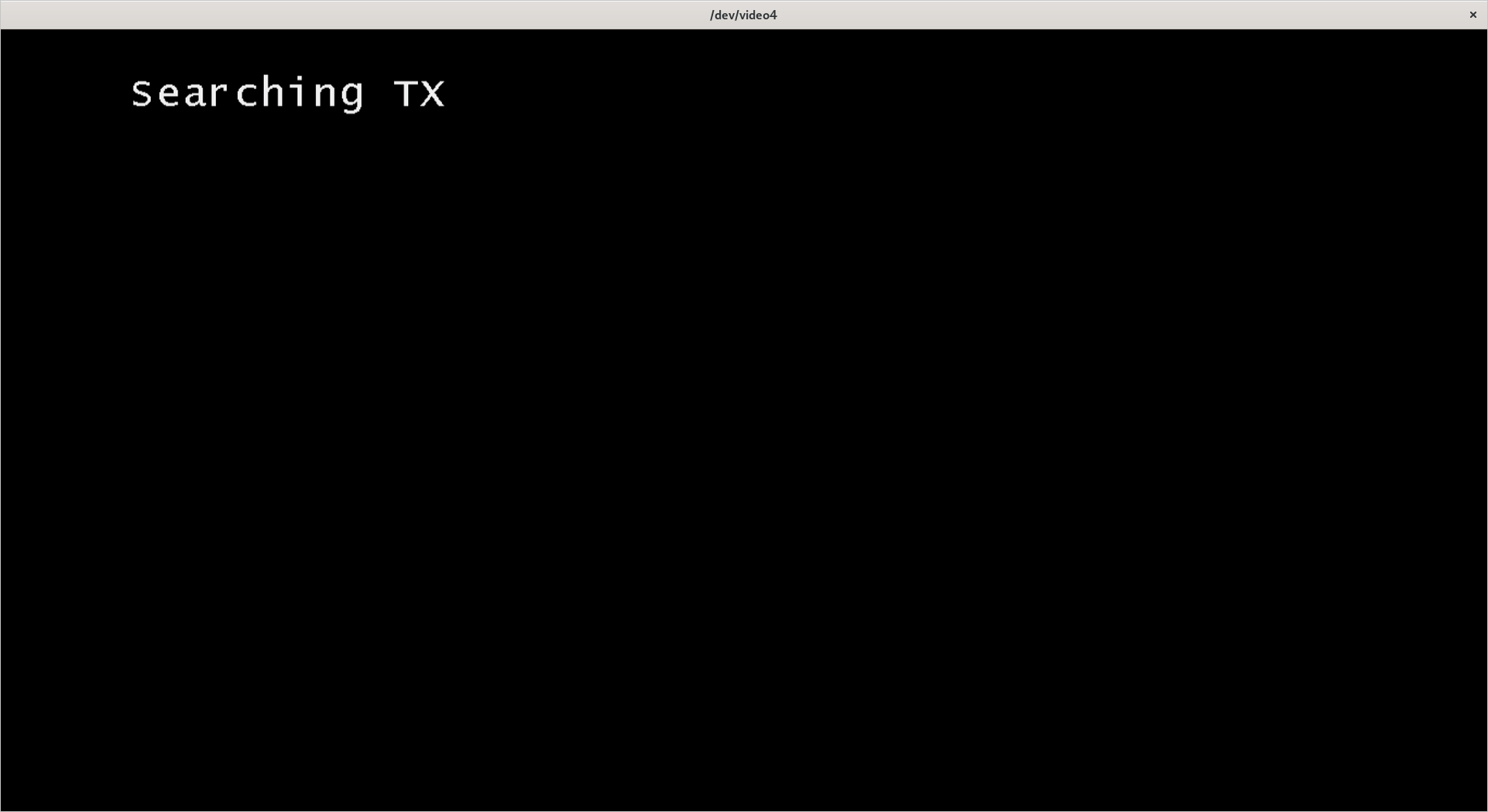
Hmm.
Let’s do the Wireshark again
I connected a real transmitter and dumped some of the packets it sends using Wireshark. Turns out there’s more stuff you need to do.
Mysterious packets on port 2067
Here’s a screenshot of some of the packets the real transmitter sends.

- the (source port) 2065 → (destination port) 2066 packets are audio data. We’ll get to those later!
- the 2068 → 2068 packets are video picture data
- …but what are these 2067 → 2067 packets?

Hmm, it’s all zeroes. What about the next one?

Aha, a byte went from 00 to 01!
Turns out this pattern continues; before each picture frame is sent, an additional packet is sent on port 2067 of length 20, with the 5th and 6th bytes being a 16-bit big-endian integer, which is the same as the frame number of the frame we just sent.
I’m guessing this is a sort of “vsync” / “vblank” packet, used to tell the receiver to get ready for a new frame. We should probably replicate it, so I wrote some code:
fn make_vsync(frame_no: u16) -> Vec<u8> {
    let mut ret = Vec::with_capacity(20);
    ret.write_all(&[0, 0, 0, 0]).unwrap();
    ret.write_u16::<BigEndian>(frame_no).unwrap();
    for _ in 0..14 {
        ret.write_all(&[0]).unwrap();
    }
    ret
}
// code to send this to port 2066 before sending frame packets elided
Alas, this was not enough. The receiver continued to say “Searching TX”.
Heartbeat packets

There are also some weird 512-byte payloads being sent on port 48689. These are easy to miss because they’re only sent once every second (and so are comparatively infrequent relative to the firehose of data the transmitters send for pictures and video). However, you can notice them by looking at the start of a packet capture since they get sent even when no picture data is being sent.
Let’s look at a dump of some of these packet payloads over time (using “[right click] Follow → UDP Stream” in Wireshark):
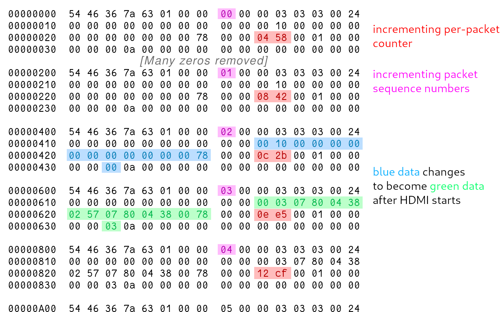
After squinting at it for a while, you notice a few things:
- The first three packets are identical, apart from a small 2-byte region that carries on going up with each new packet (marked in red), and a sequence number incremented with each new packet (marked in pink).
- Between the third and fourth packets, a large chunk of data (marked in blue) changes to something else (marked in green), and then stays that way.
- This change is also correlated with the video and audio starting.
- After the change happens the packets stay identical apart from the counter.
This must be some kind of heartbeat packet sent by the transmitter to tell the receiver that it’s there. Let’s try and figure out the various bits in the payload in more detail.
Incrementing counter
How is this counter being generated? Well, let’s assume that it’s a 16-bit big-endian integer, since everything else in this blog post has been that, and interpret the values accordingly.
0x0458is 1112, sent at time t = 0.00x0842is 2114 (delta = 1002), sent at t = 1.0010x0c2bis 3115 (delta = 1001), sent at t = 2.0020x0ee5is 3813 (delta = 698), sent at t = 2.700
Hmm…
I think it’s pretty reasonable to assume this counter just tracks time since the transmitter was powered on. Why the receiver needs that information isn’t exactly clear though (maybe for some synchronization purposes?).
Anyway, we should probably do the same as the transmitter when sending our own packets here so we’ll add a timer to the code.
Other gubbins
We have two sets of weird data:
00 03 07 80 04 38 02 57 07 80 04 38 00 78 03(when the HDMI port is active)00 10 00 00 00 00 00 00 00 00 00 00 00 78 00(when it isn’t)
07 80 and 04 38 are repeated multiple times. Let’s try decoding those
as 16-bit big-endian integers:
0x0780is 19200x0438is 1080
That seems familiar; isn’t 1920×1080 the resolution for 1080p? This data is presumably used to initialize the HDMI port on the other end.
What about when the HDMI is off? Well, it looks like most of the fields are just zeroed out, which makes sense since it doesn’t have a resolution or anything to send yet. (This causes the message “Check Tx’s input signal” to appear on the receiver, which is useful for debugging why the receiver isn’t displaying anything.)
In the end, I just encoded all of this data as constants (interpreting it as a set of 16-bit big endian integers), sending one set (the one with 1920s in it) if we’re ready to send data, and another set (the zeroed out set) if we aren’t.
Putting it all together
The code to make a heartbeat packet ended up looking like this:
fn make_heartbeat(seq_no: u16, cur_ts: u16, init: bool) -> Vec<u8> {
    let mut ret = Vec::with_capacity(512);
    ret.write_all(&[0x54, 0x46, 0x36, 0x7a, 0x63, 0x01, 0x00]).unwrap();
    ret.write_u16::<BigEndian>(seq_no).unwrap();
    ret.write_all(&[0x00, 0x00, 0x03, 0x03, 0x03, 0x00, 0x24, 0x00, 0x00]).unwrap();
    for _ in 0..8 {
        ret.write_all(&[0]).unwrap();
    }
    // woohoo, magic numbers
    let (mode, a, b, c, d, e, f, other) = if init {
        (3, 1920, 1080, 599, 1920, 1080, 120, 3)
    }
    else {
        (16, 0, 0, 0, 0, 0, 120, 0)
    };
    for thing in &[mode, a, b, c, d, e, f] {
        ret.write_u16::<BigEndian>(*thing).unwrap();
    }
    ret.write_all(&[0, 0]).unwrap();
    ret.write_u16::<BigEndian>(cur_ts).unwrap();
    ret.write_all(&[0, 1, 0, 0, 0, 0, other, 0x0a]).unwrap();
    for _ in ret.len()..512 {
        ret.write_all(&[0]).unwrap();
    }
    assert_eq!(ret.len(), 512);
    ret
}
Putting it all together and sending heartbeat packets, vsync packets, and the actual picture data… got the receiver to initialize, but output a black rectangle instead of the test image.
After trying many other things, I eventually tried sending the original test.mjpeg file
I’d dumped from the receiver when first trying to get this to work, instead of my own
JPEG that I made in GIMP. That actually produced some output!
Yay!
(the test image was produced by writing some text on a laptop, making it full-screen, and connecting it to the transmitter)
But what about audio?
While this is (somewhat) useful, it doesn’t do what we originally wanted; what about actually sending audio?
How does digital audio work, anyway?
Digital audio is represented as a series of samples – individual measurements of what the voltage of your speaker should be at a given point in time (the “signal”), taken at a given sampling rate that’s high enough to provide a decent approximation of what the speaker should be doing to reproduce your favourite tunes.
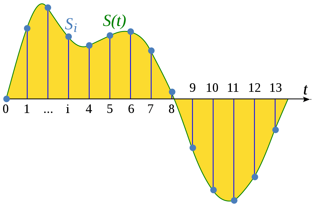
image: sourced from the above linked Wikipedia article, CC0
There are a number of important variables involved in this process that we need to know in order to send and receive audio in a given format:
- what the sample rate was (measured in Hertz, aka “times per second”)
- how the samples are stored (as floating-point numbers? as signed integers? how many bits?)
- what the “maximum” and “minimum” values are (for floats, we typically use
1.0and-1.0; integer formats useINT_MAXandINT_MIN)
What format do the extenders use?
de-ip-hdmi has already figured this out for us:
if audio {
    ffmpeg = exec.Command("ffmpeg", "-f", "mjpeg", "-i", uuidpath, "-f", "s32be", "-ac", "2", "-ar", "44100", "-i", "pipe:0", "-f", "matroska", "-codec", "copy", "pipe:1")
}
This is a ffmpeg command line that de-ip-hdmi uses to wrap the data from the extenders in a Matroska container
(a way of combining audio and images together into one video file). We can tell a few things from this:
-f s32be: the samples are stored as signed 32-bit big-endian integers- this uses
i32::MINandi32::MAXas minimum/maximum (i.e. -2147483648 and 2147483647)
- this uses
-ac 2: there are 2 audio channels- the samples from each channel will be interleaved, since we just have one big audio stream
-ar 44100: the sample rate is 44100 Hz
It looks like de-ip-hdmi just treats everything after the 16th byte as a set of samples in the above format:
// Maybe there is some audio data on port 2066?
if pkt.Data[36] == 0x08 && pkt.Data[37] == 0x12 && *output_mkv && *audio {
    select {
    case audiodis <- ApplicationData[16:]:
    default:
    }

    continue
}
Going back to our Wireshark dump, the first 16 bytes of every audio packet seem to be identical (and the packets are always 1008 bytes long):

So, to send audio data we should in theory be able to write the header and then 992 (1008 - 16) bytes worth of samples into a packet and send it as UDP from port 2065 to port 2066.
However, how frequently should we send the packets?
Timing is everything
We need to provide 44100 × 2 = 88200 samples each second, since we have 2 audio channels at 44100 Hz sample rate. Each packet of audio
contains 996 bytes of samples at 32 bits (= 4 bytes) per sample, so 992 / 4 = 248 samples fit in a packet.
That means we need to send a packet every 248 / 88200 seconds, or roughly 2.812 milliseconds (to 3 decimal places) – which seems to line
up with the frequency observed in the Wireshark dump:
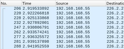
(e.g. 2.9222 s - 2.9195 s = 2.7ms, 2.9251s - 2.9222s = 2.9ms, etc)
I wrote up some sample code that read samples from stdin (fed in using ffmpeg) and sent a packet, then slept for 2812 nanoseconds, and then repeated.
This resulted in…complete silence!
That is, until we changed the device connected to the HDMI receiver unit (a hifi system with HDMI passthrough) to another device (a projector). The projector happily played the audio we were sending… but it sounded distorted (kinda “crunchy” sounding). What’s going on?
Jitter is unacceptable
A while ago, I wrote some audio code for a project called “SQA”. This taught me one of the ‘cardinal rules’ of audio programming: jitter is unacceptable. There’s a great blog post called “Real-time audio programming 101: time waits for nothing” that explains this in more detail but to sum up: when supplying audio samples for playback, you have a fixed amount of time to fill a buffer of a certain size, and you must always fill the buffer in the time given to you (or less).
If you leave the buffer half-filled the audio will “glitch”: it’ll have pops and clicks in it and/or sound distorted, because the new samples you’ve only half written will stop halfway through the playback buffer and jump suddenly to a bunch of zeroes instead (or some other garbage data). This is called a buffer under/overrun, or an xrun for short.
So, how do you make sure you never glitch? Well, doing anything that could block or take lots of time to complete (reading from a file, waiting on a mutex, etc.) in the thread that handles audio is strictly forbidden; you’ve basically got to have something else put the audio samples in a ringbuffer for you to copy out in the audio thread.
Final audio thread code
Armed with the above knowledge, I completely rewrote the audio thread – and it actually works!
It now uses the excellent bounded_spsc_queue ringbuffer library to ship samples from the rest of the program
and the audio thread, and spin-waits (loops) until it needs to send the next packet.
(Doing the “proper” thing and using something like nanosleep(2) would be more efficient – but was unreliable
compared to just spinning in my tests.)
The full audio thread code is below:
fn audio_thread(udp: UdpSocket, dest: SocketAddr, queue: Consumer<u8>) {
    let mut pkt = [0u8; 1008];
    // Pre-write the header on to the packet.
    for (i, b) in [0, 0x55, 0x55, 0x55, 0x55, 0x55, 0x55, 0x55, 0x55, 0x55, 0x55, 0x55, 0, 0, 0].iter().enumerate() {
        pkt[i] = *b;
    }
    let now = Instant::now();
    // Monotonic nanosecond counter.
    let cur_nanos = || {
        Instant::now().duration_since(now).as_micros()
    };
    // 2.812 milliseconds!
    const INTERVAL: u128 = 2812;
    // Next time (on the counter) we need to send a packet.
    let mut next = INTERVAL;
    // Current buffer pointer.
    let mut ptr = 16;
    // Consecutive Xrun counter.
    let mut num_xruns = 0;
    loop {
        let cur = cur_nanos();
        if cur >= next {
            // Send the packet.
            udp.send_to(&pkt, &dest).unwrap();
            // Check if we managed to fill the buf; if not, we've xrun'd.
            if ptr != 1008 {
                num_xruns += 1;
            }
            else {
                // Reset the pointer.
                ptr = 16;
                num_xruns = 0;
            }
            // Advance the deadline so it's 2.8ms after the previous one.
            // We skip over if we're already going to miss it.
            while cur >= next {
                next += INTERVAL;
            }
        }
        // Okay, now time to fill the buffer a bit.
        if ptr < 1008 {
            if num_xruns > 5 {
                // Let's just fill it up with silence instead.
                // (otherwise you get a buzzing effect that's highly irritating)
                pkt[ptr] = 0;
                ptr += 1;
            }
            else {
                if let Some(smpl) = queue.try_pop() {
                    pkt[ptr] = smpl;
                    ptr += 1;
                }
            }
        }
        else {
            ::std::thread::yield_now();
        }
    }
}
Conclusions
The code is here. Don’t expect miracles. (If you actually plan to use this, you might want to get in touch.)
There are a number of ways to feed data into it, which you choose at compile time using Cargo features. You can either feed in raw s32be samples from either stdin or TCP (it’ll make a TCP server and you can connect and send stuff, but not with more than one client at the same time…). I also ended up adding a JACK backend (using my own sqa-jack library), if that’s your thing.
 (eta)
(eta)