A guide to STM32F103 microcontrollers - part 1
So, there are these cheap microcontrollers I’ve recently started looking into
based off the STM32F103
architecture, which itself belongs to the Arm Cortex-M3 processor family.
I originally looked into them because they’re actually full 32-bit processors
instead of the 8-bit kind usually found on an Arduino Uno,
which uses the 8-bit ATmega328P
processor. This means that they’re a lot easier to work with (you can actually
have native 32-bit integers…!), way faster than their AVR competitors - and, as an added bonus, you can do cool things
like run Rust on them, with the stm32f103xx-hal crate.
However, documentation on them is rather scarce and fragmented, given that these processors don’t have the same kind of community around them that Arduino users can benefit from. Therefore, I’m going to do a blog series about them, summarizing what I’ve learnt while using them, in the hope that it might be useful to someone else!
This first post mainly focuses on what hardware is available, and how to configure it to upload simple code. It’ll get more interesting in later posts, though!
Origins
The STM32F103 originally made its fame through the Maple Mini and Maple Arduino clones made by
a company called LeafLabs, which no longer manufactures them. However,
LeafLabs built a whole bunch of tooling to let you write code for these
boards as if they were Arduinos (using digitalWrite(), pinMode(), and other
familiar Wiring-style functions). This lives on as the open-source
STM32duino project,
and a lot of the info in this blog post comes from their wiki.
Buying
There are two main boards (that I’ve heard of and tried personally): the Maple Mini, and the Blue Pill. I got mine off Amazon UK; I believe it’s also possible to get these boards via AliExpress or eBay, if you prefer.
(You’ll have to excuse my terrible soldering in the following photos…)
Maple Mini
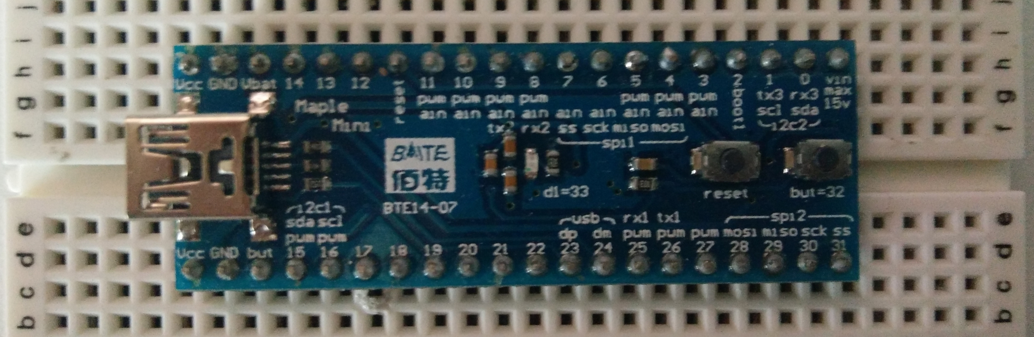
link to STM32duino wiki · buy for £9 on Amazon (affiliate link)
As discussed above, this is the most supported STM32 board, and it’s pretty much plug & play. Mine seemed to come with the bootloader preloaded, making things even easier; if that isn’t the case, it’s not too hard to reflash it (I had to do so myself after botching an upload).
The USB port is a miniUSB, not a microUSB, which can be a bit annoying given how many things use microUSB nowadays.
A pinout is available on the wiki link above; notably, this board uses its own naming scheme for the pins, and you have to use this table to convert between those and the actual GPIO names if you want to program it in Rust or use something apart from the STM32duino environment.
Blue Pill
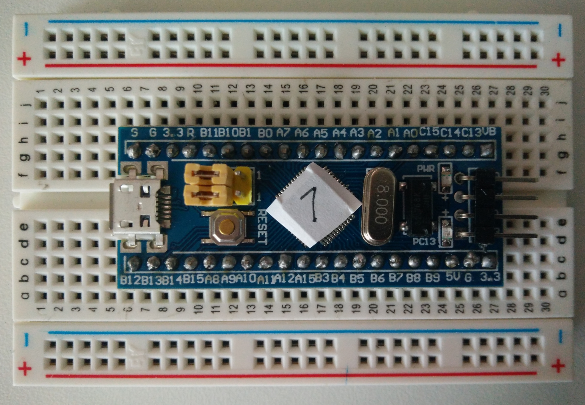 link to STM32duino wiki · buy for £6 on Amazon (affiliate link)
This board is £3 cheaper than the Maple Mini (in fact, if you buy it from not-Amazon, it costs about $2), but has a number of drawbacks. Firstly, the on-board voltage regulator (used to convert from 5V to 3.3V) is lousy, meaning that you can’t draw much current (more than 100mA) from any of the pins on the board, or you risk frying the whole thing (if the regulator fails, it passes the 5V through to the STM32 directly, breaking it).
You also can’t power the thing with USB power and external 5V power, otherwise it breaks, and some PCs may refuse to work with its USB interface due to an incorrect pull-up resistor on one of the data lines. Despite that, though, the Blue Pill is still pretty useful.
Unlike the Maple Mini, its pins are actually labeled in a sane manner; like the Maple Mini, there’s also a pinout diagram on the STM32duino wiki link above.
Tools
While it is possible to upload code to the Maple Mini via USB only, the Blue Pill requires one of the below tools to upload anything (you can flash a bootloader that lets you upload via USB, and then do that, but you still need the tool for the first flash).
ST-Link
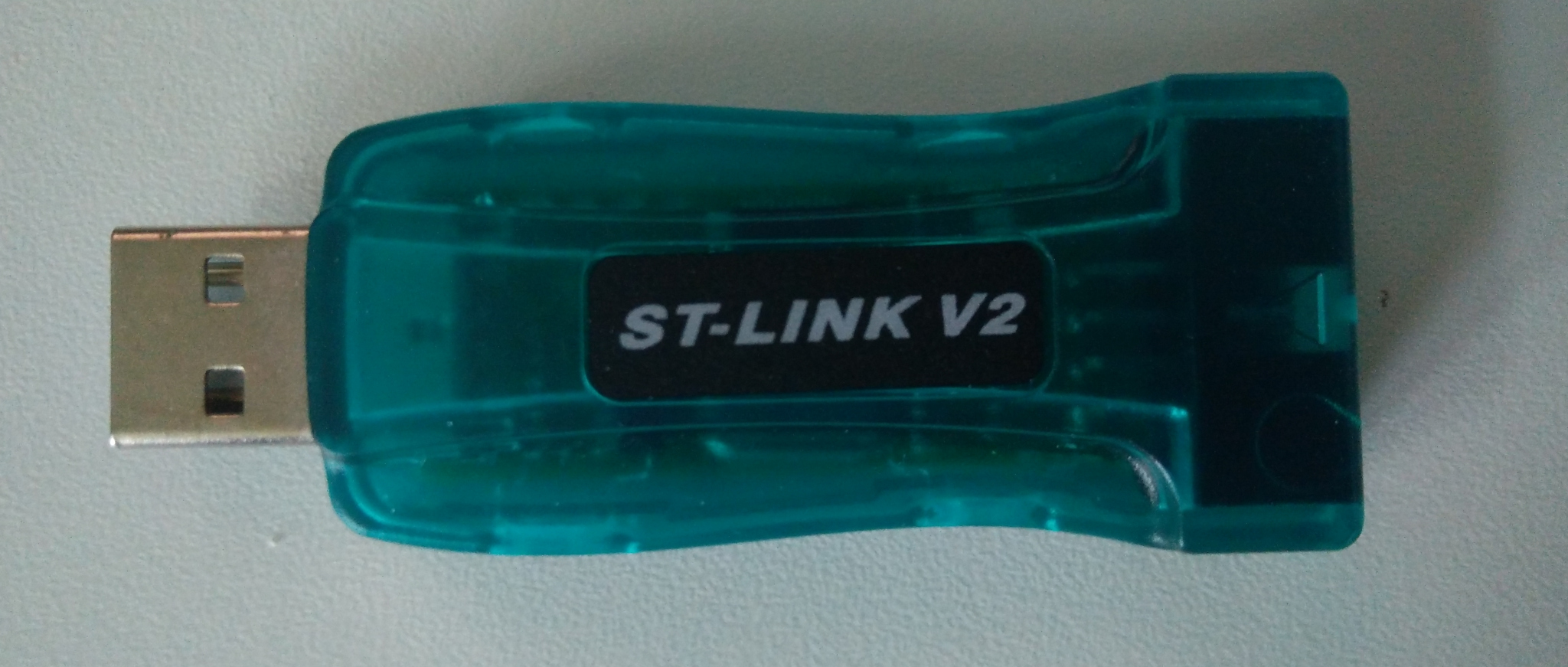
buy for £9 on Amazon (affiliate link)
The ST-Link is ST Microelectronics’ tool for flashing STM32-based boards. It’s pretty handy to have - not only does it let you program the board, but it also provides on-chip debugging support, allowing you to pause the program mid-execution, inspect variables, etc.
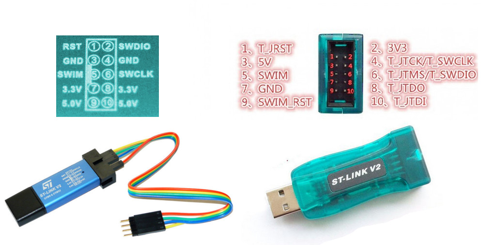
The pinout varies depending on which kind you end up with - see the below diagram (the one pictured above is the one on the right below).
USB to TTL serial adapter
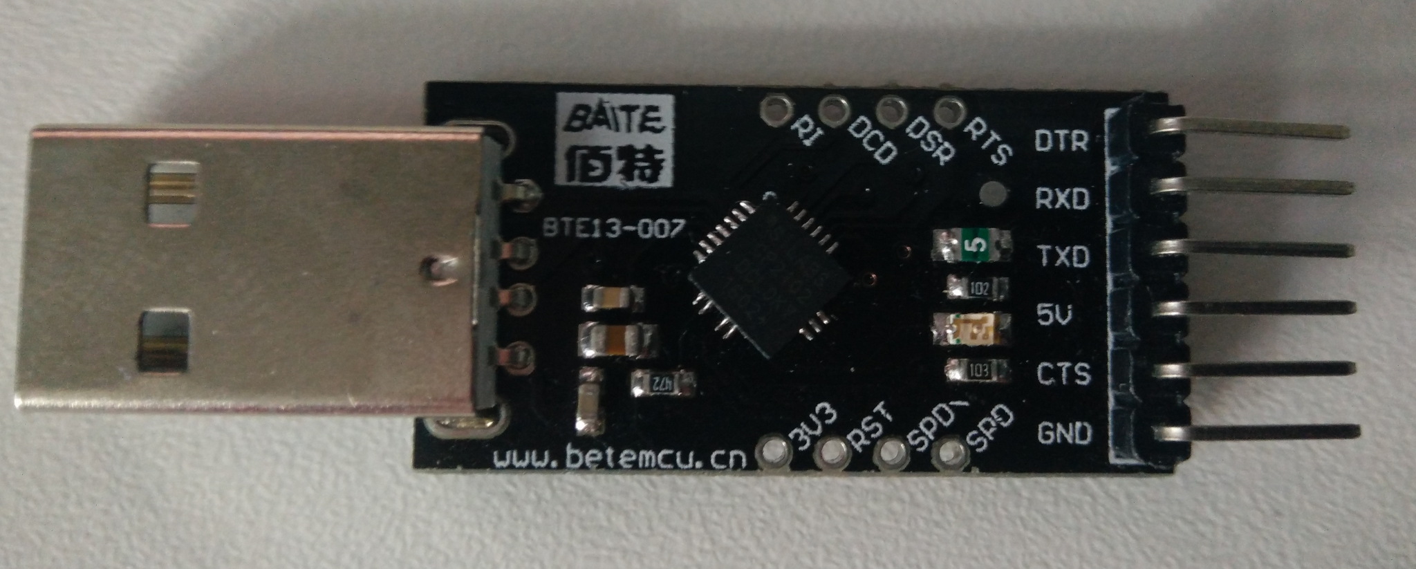
buy for £6 on Amazon (affiliate link)
This is just a handy tool to have anyway - for example, if you want to send data using one of the boards’ USART interfaces and receive it using this thing. Incidentally, this also works with the serial console connection on a Raspberry Pi.
For STM32 boards, this can be used to upload code if you don’t have a ST-Link (q.v.).
STM32duino
This section details how to use the STM32duino IDE and firmware. This is probably the easiest way to write code for these boards at present, and there are 3 ways (that I’ve tested) to upload code to the boards: via the bootloader (very easy), with a USB to TTL serial adapter, and with an ST-Link.
Install the IDE and software
Follow the STM32duino Installation guide. You can ignore the “Burning the bootloader” bit for now, as we’ll cover that in more detail later - if you want to use the bootloader method, jump ahead to the relevant section below. I’ve tested it with Arduino IDE 1.8.7, so you can probably ignore the bit about 1.8.5 being the latest supported version.
Upload code - using the bootloader
If you’re using a Maple Mini, or have installed the USB bootloader for the Blue Pill, uploading code is pretty easy. However, note that this method is incompatible with any of the other methods - uploading code with another method will mean that you’ll need to flash the bootloader again (see below).
- Open the Arduino IDE, and go to File → Examples → A_STM32_Examples → Digital → Blink to load the example blinking LED code.
- If you’re using a Blue Pill, change
PB1toPC13where it appears in the code.
- If you’re using a Blue Pill, change
- Go to Tools → Board, and choose the appropriate board type.
- “Maple Mini” is, unsurprisingly, the option for a Maple Mini.
- Choose “Generic STM32F103C series” for a Blue Pill.
- If you’re using a Blue Pill, change Tools → Upload method to “STM32duino bootloader”.
- Change Tools → Port to the serial port for your microcontroller (it should be fairly obvious; there’s usually only one entry).
- Hit Upload (the right-facing arrow on the main toolbar).
- If it doesn’t work, you might need to press the Reset button on the MCU before trying again; occasionally, you need to time it just right.
- On the Maple Mini, you can hold the second button (
but=32) after pressing Reset to keep it in the bootloader, making uploading somewhat easier. - You also need to ensure that you have permission to write to the serial port
(usually
/dev/ttyACM0or/dev/ttyUSB0). This might entail installing these udev rules, adding yourself to theplugdevgroup, or something else; consult your Linux distro’s documentation.
- Observe blinking LED.
Upload code - using a serial adapter
STM32F103 chips have an internal mode built into the chip that lets you flash programs via a USB to TTL serial adapter, such as the one featured above. This has different setup instructions depending on the board you’re using.
(This is also a relatively easy way to upload code to a Blue Pill without futzing around with the ST-Link.)
Blue Pill
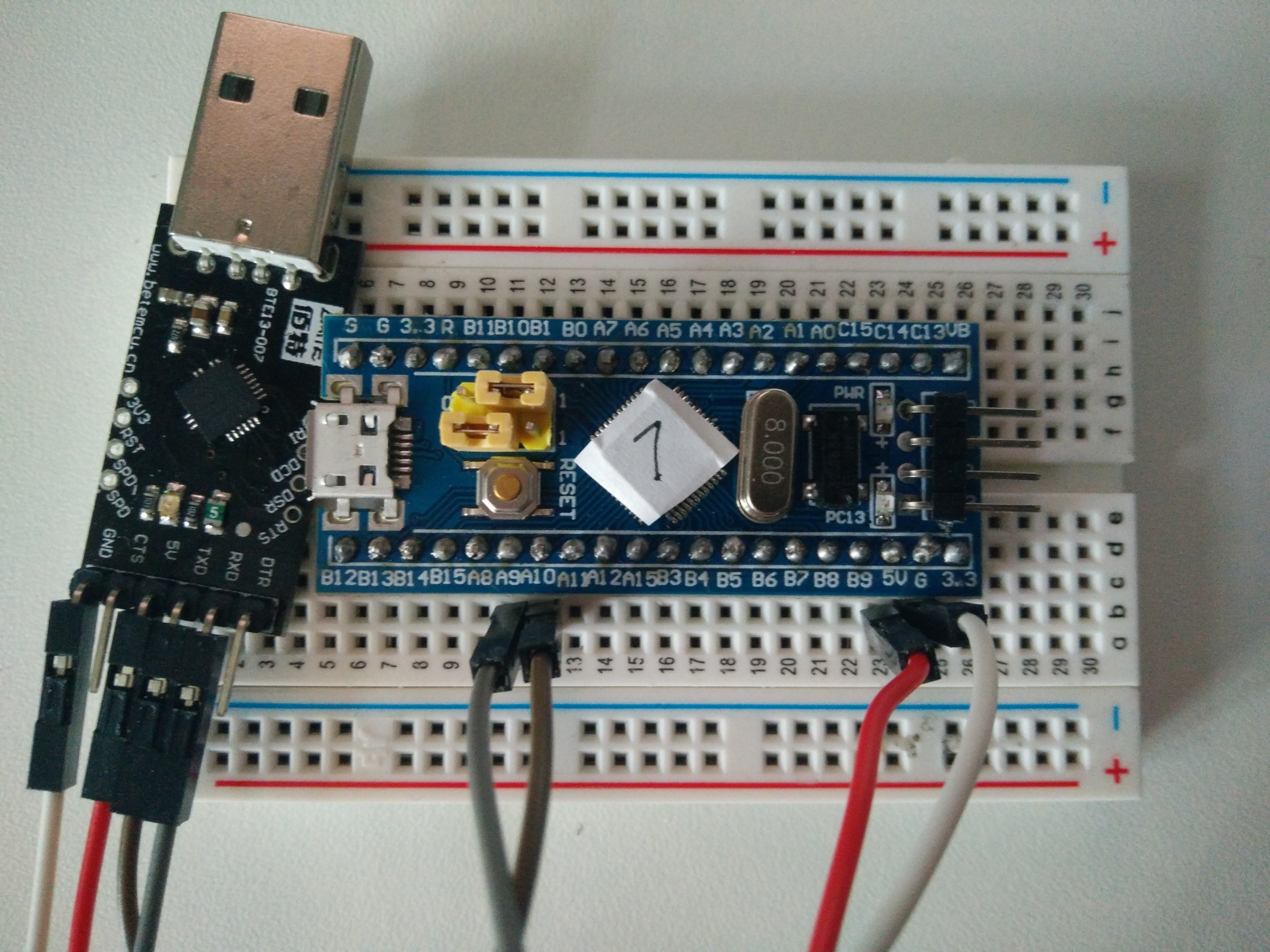
For the Blue Pill, wire up 5V and GND from your serial adapter to the identically-named pins on the board.
Then, connect RX on your serial adapter to A9 on the board, and TX to A10.
You’ll also need to ensure that the jumpers (e.g. the yellow thingies above the RESET button) are set in the correct position.
- During normal operation (i.e. when running stored code), the jumpers should both be in the
0position. - To flash code using this method, the top jumper (closest to
B10) should be in the1position, with the other left in0.
Do remember to restore the jumper to the correct position after uploading!
Maple Mini
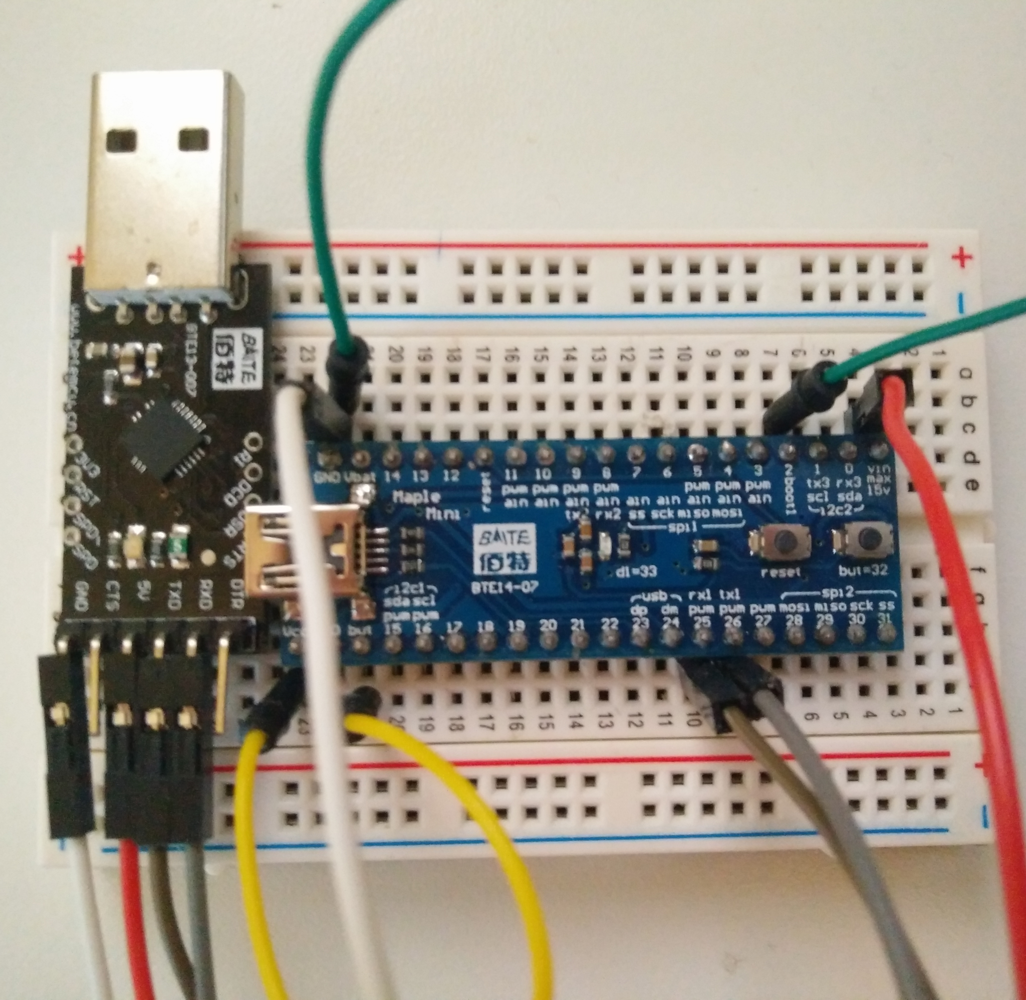
For the Maple Mini, wire up 5V on the adapter to Vin on the board, GND to GND, RX to 26 (tx1),
and TX to 25 (rx1). Then, connect but (aka Boot 0) on the board to Vcc, and 2 (aka Boot 1) to GND.
You’ll need to remove the connections from but and 2 after you’ve finished flashing
if you want the board to run on its own (rather like the jumpers on the Blue Pill).
Method
- Open the Arduino IDE as before, and go to File → Examples → A_STM32_Examples → Digital → Blink to load the example blinking LED code.
- If you’re using a Blue Pill, change
PB1toPC13where it appears in the code.
- If you’re using a Blue Pill, change
- Go to Tools → Board, and choose “Generic STM32F103C series” (even if you have a Maple Mini).
- Change Tools → Upload method to “Serial”.
- Change Tools → Port to the serial port for your TTL serial adapter (it should be fairly obvious; there’s usually only one entry).
- Hit Upload (the right-facing arrow on the main toolbar).
- If you get errors, check you have permissions to write to the serial port,
and that you’ve connected
TXandRXcorrectly.
- If you get errors, check you have permissions to write to the serial port,
and that you’ve connected
- Observe blinking LED.
Upload code - using a ST-Link
This works like the serial method, but with far less wiring (you don’t have to change any jumpers). Once again, setup instructions differ depending on board.
Blue Pill
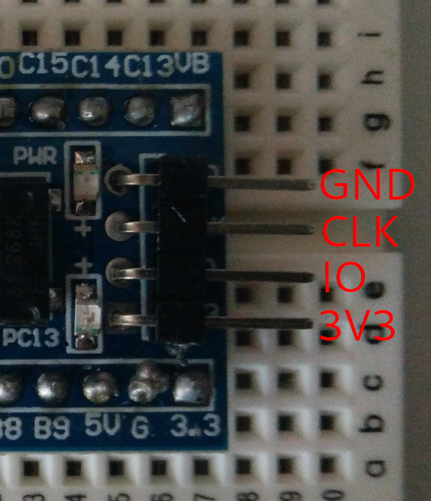
Use the ST-Link pinout diagram from above. Connect the 4 pins on the 4-pin programming
header on the right of the board, from top to bottom, to GND, SWCLK, SWDIO,
and 3V3 (or 3.3V) on the ST-Link. (i.e. GND should be at the top, next to the
pin labeled 3VB, and 3V3 next to the pin labeled 3.3).
Maple Mini
Use the ST-Link pinout diagram from above. Connect 3V3 on the ST-Link to Vcc
on the Maple Mini, GND to GND, SWCLK to 21, and SWDIO to 22.
Method
- Open the Arduino IDE as before, and go to File → Examples → A_STM32_Examples → Digital → Blink to load the example blinking LED code.
- If you’re using a Blue Pill, change
PB1toPC13where it appears in the code.
- If you’re using a Blue Pill, change
- Go to Tools → Board, and choose “Generic STM32F103C series” (even if you have a Maple Mini).
- Change Tools → Upload method to “STLink”.
- Hit Upload (the right-facing arrow on the main toolbar).
- Observe blinking LED.
Command-line flashing
In this section, connect up the boards as described in the STM32duino section earlier. These instructions only work for Linux at the moment.
You can compile a STM32duino sketch into a flashable binary using Sketch → Export compiled binary in the IDE; the binary will be placed in your sketch folder. We’ll cover how to create programs without the STM32duino IDE in a later blog post.
All of the tools required in this section can either be installed from your Linux
distribution’s package manager, or you can install the STM32duino IDE, which
contains a copy in hardware/Arduino_STM32-master/tools/linux/ - stm32flash
is found in stm32flash/, dfu-util in dfu-util/ and st-{info, probe} in stlink/.
Depending on your installation, Arduino_STM32-master may be called something else
(it may not have the -master suffix, for example).
Via serial adapter
On Arch Linux, install the stm32flash package from the AUR. Similar packages
may be available for other distributions.
Flash a binary
$ stm32flash -g 0x8000000 -b 115200 -w BINARY /dev/ttyUSB0
…writes BINARY to the flash memory of the board connected to the /dev/ttyUSB0 serial adapter.
You might need to change /dev/ttyUSB0 to, for example, /dev/ttyACM0; look in
dmesg to figure out what your serial adapter is called.
ST-Link
On Arch Linux, install the stlink package (# pacman -S stlink). Similar packages
may be available for other distributions.
As discussed earlier, the ST-Link also allows you to perform live debugging.
Check connections
$ st-info --chipid
Should return a non-zero value (mine says 0x0410). If it returns nothing or 0x0000,
check that everything is connected correctly.
If you have a newer version of
the stlink tools, st-info --probe may also tell you some interesting information.
Flash a binary
$ st-flash write BINARY 0x8000000
…writes BINARY to the flash memory of the connected board.
GUI
If you installed the stlink package, you might also be able to run
$ stlink-gui
to get a neat GUI interface for doing things. Nifty!
Via USB
On Arch Linux, install the dfu-util package (# pacman -S dfu-util). Similar
packages may be available for other distributions.
There are two ways to upload something via USB: you either cave in and use
the maple_upload script from the STM32duino tools, which saves you a lot of pain,
or you decide to only use dfu-util.
Using maple_upload
The maple_upload script lives in hardware/Arduino_STM32-master/tools/linux,
and is invoked like so:
$ ./maple_upload ttyACM0 2 1eaf:0003 BINARY
You might need to replace ttyACM0 with ttyUSB0 if your board or Linux kernel
is different to mine. This uploads BINARY to the board, resetting it properly
before and after to make everything work with minimal stress.
I still don’t know why 2 is specified (for an option called altid), but it works.
Using dfu-util
To do this, you need to have one hand on the RESET button and one hand on the Enter key, with this command pre-typed. You might have to try it a number of times before it works, and you might also need to try unplugging & reinserting the USB cable.
$ dfu-util -d 1eaf:0003 -a 2 -D BINARY -R
This uploads BINARY to the board, and doesn’t do much else. You’ll want to unplug and reinsert the board after uploading, otherwise future uploads might fail for some mysterious reason.
Burning the bootloader
This is required if you want to upload via USB with the STM32duino IDE. You’ll need to use one of the command-line methods above (apart from USB, of course).
Blue Pill
Download generic_boot20_pc13.bin,
and flash it to the board using one of the command line flashing methods.
To recap, that means connecting up a serial adapter or ST-Link as described
in the STM32duino section, then running the relevant command from the Command
line flashing section, replacing BINARY with the path to generic_boot20_pc13.bin.
For example:
$ wget https://github.com/rogerclarkmelbourne/STM32duino-bootloader/raw/master/binaries/generic_boot20_pc13.bin # download the bootloader

For ST-Link:
$ st-flash write generic_boot20_pc13.bin 0x8000000
For a serial adapter connected to /dev/ttyUSB0:
$ stm32flash -g 0x8000000 -b 115200 -w generic_boot20_pc13.bin /dev/ttyUSB0
Maple Mini
As above, except you’ll need maple_mini_boot20.bin instead.
Conclusion
That’s pretty much all I have to say about the basics of working with STM32 boards, hardware-wise. In future blog posts, we’ll explore how to write programs with toolchains more interesting than just the STM32duino IDE - for instance, how to use Rust and its growing embedded ecosystem, or perhaps how to use the more traditional C HAL libraries to get a bit closer to the metal. Thanks for reading!
(If you’d like to be notified of new posts, there’s a RSS link below in the footer!)
Syndications
This blog post has been syndicated to the following places (feel free to leave a comment there!):