Building the Physics Penitentiary
(Edited 2019-08-06: added links to download the source code, and made a few minor language changes.)
I recently took part in the Weizmann Institute’s international “safe-cracking” tournament, as part of a team of five people who placed highly enough in the UK version of the tournament to get to fly over to Israel and have a shot it it over there. Since I did most/all of the electronics and control system for our entry, I thought I’d write a blog post about it!
Essentially, the idea behind the competition is to build ‘safes’ - essentially boxes with physics-related puzzles and challenges that must be completed in order to ‘crack’ the safe, with the point being that only an understanding of the physics involved would let you unlock it. Our safe, the Physics Penitentiary1, looked a bit like this:
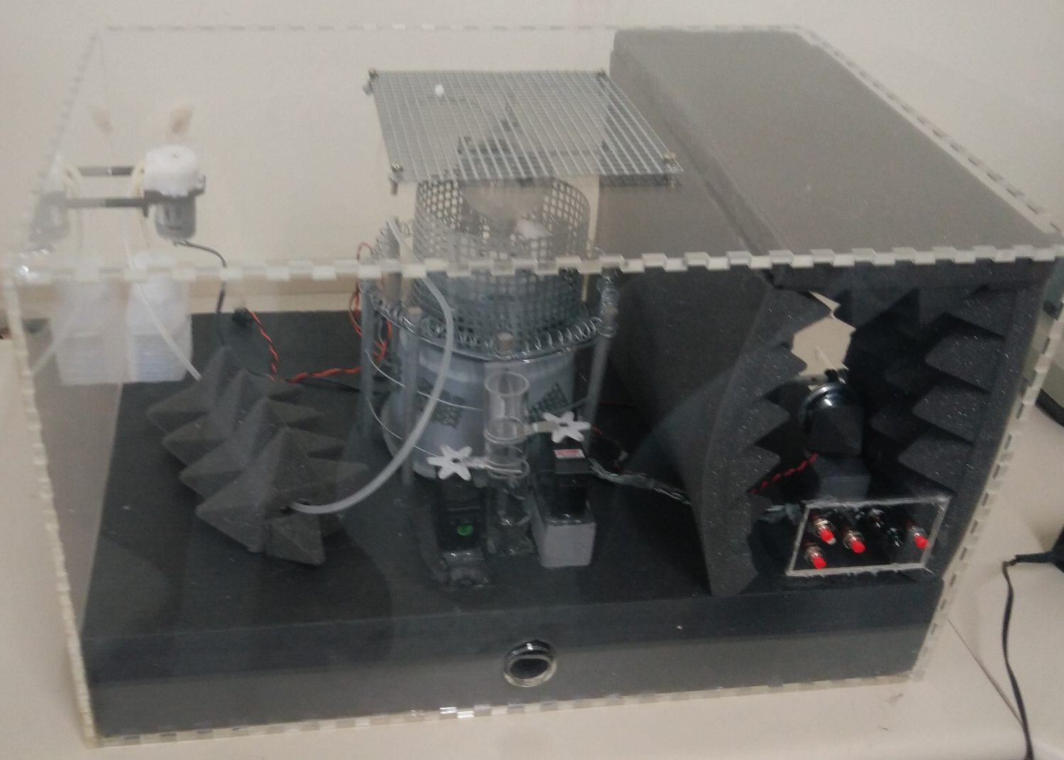
Safe background
So, I’m not a physicist by any means (which led to some fun discussions about what a random CS student was doing taking part in a physics competition, but we’ll gloss over that…), which means I have only a loose understanding of the physics. That aside, what was in the safe roughly looked like:
- one Crookes radiometer / light mill (the weird glass thing in the very centre, surrounded by a cage)
- a pump, hooked up to a container full of ethanol, arranged to deposit said ethanol on the radiometer
- a soundproof(-ish) section to the right, with two speakers facing one another, plus a microphone
- a control panel with lots of fun buttons for the user to press
- a tube with two servo-controlled flags blocking it, which was used to dispense marbles (‘prisoners’) upon successful completion of the challenges
In addition to this, you were allowed:
- two torches, one with a tungsten bulb, one LED
- a canister of compressed air
With this, you had to ‘crack’ the safe by figuring out how the Crookes radiometer worked - essentially, due to some physicsey explanation I don’t quite comprehend2, the radiometer would spin if it was heated (e.g. by shining an inefficient tungsten bulb on it), and would also spin, but in the opposite direction, if you cooled it again (e.g. by inverting the canister of compressed air to get at the incredibly cold gas and spraying that on the surface of the radiometer). We also added the sound-based challenge seen to the right, where you had to get the two sound waves to match frequency and wave type (e.g. sine, square, or triangle) in order to cancel each other out3 - to make it a bit harder, and also to fit with the ‘prison’ theme.
Above: nifty GIF of the radiometer doing its thing. Image courtesy of Nevit Dilmen on Wikimedia.
And that was all well and good; the thing spun one way if you used the light, and spun the other way if you used the inverted gas canister.
However, one important detail is still missing: how did the safe actually detect which way the radiometer was spinning, if at all? In planning, we sort of hand-waved this issue away with vague talk of ‘lasers’, ‘infrared’ and ‘proximity sensor hackery’, but it turned out that detecting the spin direction was one of the hardest challenges we had to solve - and the solution was nearly all in code as well, which makes it interesting to talk about!
You spin me right round, baby, right round
So, we had a problem. The problem was made harder by a number of restrictions:
- The radiometer was a completely sealed partial vacuum chamber, so we couldn’t get in there to add sensors or machinery of any sort. Anything we’d want to use to detect the spin would have to be outside.
- It’s curved glass, so using a laser, IR beam or something like that probably wouldn’t work too well (though we didn’t test it) due to the light being bent (i.e. refraction).
- The method used to cool the radiometer (shooting freezing cold liquid at the glass through the grating at the top) caused it to frost over with an
opaque white layer of ice. If any sensors were in the way of this blast, they probably wouldn’t have fared too well.
- To remedy this issue, the ethanol dispenser would let you spray ethanol on the glass to defrost it, making it clear again - although, of course, this also meant the sensors had random extra liquids to contend with…
In the first revision of the safe (the one that we presented at the UK finals), this was accomplished using a generic proximity sensor we managed to procure from eBay pointed at the radiometer, and some very very questionable heuristics - to give you an idea, we only managed to get the heuristics to work semi-reliably on the very day of the competition itself, and even then, the output of the sensor detection algorithm was fed into an array of 5 recent readings, and we’d take the majority value out of these five to smooth out the inconsistencies (!)4. Very little science was involved in getting this to work; we5 just threw code at the problem until something semi-worked.
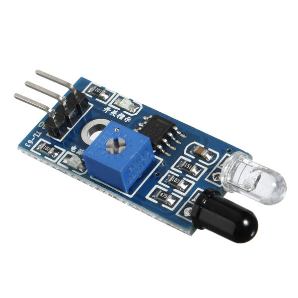
Needless to say, such a solution was not going to fly (quite literally6) at the international competition, so, after our miraculous success at the national finals, we needed to think of something else.
The solution we eventually settled on involved using a Vishay VCNL4010 proximity sensor (and SV-Zanshin’s wonderful Arduino library). This sensor had a number of nice features that made us choose it:
- The actual sensor block (the small black square in the linked image) was very tiny - in fact, just smaller than one of the blades of the radiometer. This meant we could position it such that the block lined up exactly with the blades, so we’d get actually decent readings.
- It had a built-in ambient light sensor, and combined this data with the IR proximity data to avoid ambient light messing up the sensor readings, which was an issue with the old sensor. As a bonus, this feature actually worked - shining a light on the radiometer didn’t seem to affect the sensor at all!
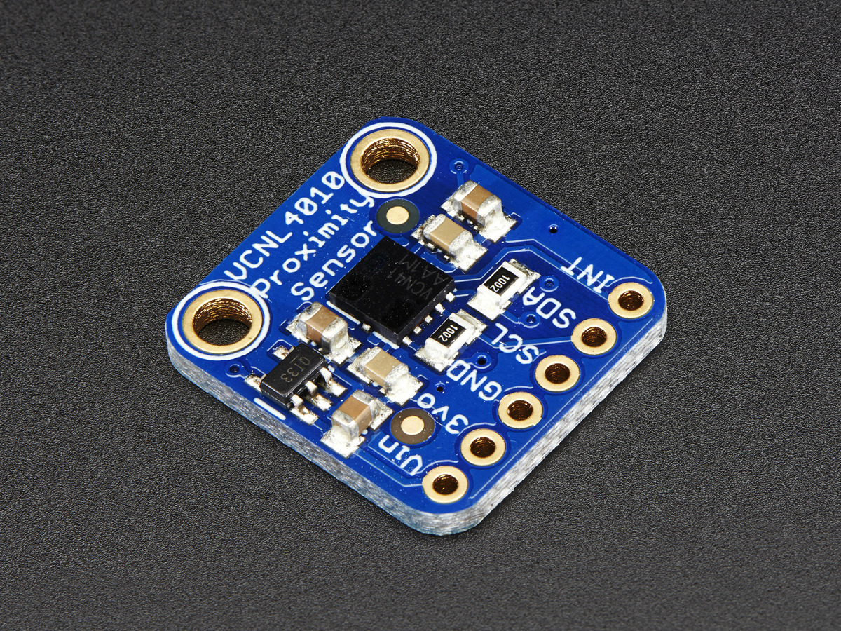
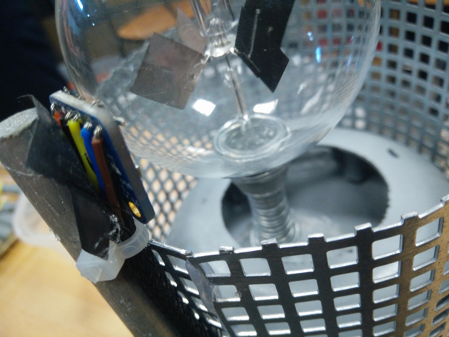
Above: one of the pictures we took of the sensor alignment during testing. Note the neat use of braided sheathing to make cable management not painful…
It’s graph time!
With the actual hardware sorted out, as best we could (positioning the sensor was painstakingly hard, and required multiple attempts to get it to work properly), the next remaining challenge was actually making sense of the proximity data.
Of course, a proximity sensor only gives you a reading indicating how near or far something is, in arbitrary units; you still need to do some processing to figure out spin direction (spin frequency is relatively easy to determine, but we didn’t really care about that much here). In theory, this should be relatively easy: if the sensor is spinning in one direction, the proximity should be increasing (modulo the spike down every now and then), and vice versa for the opposite direction. Indeed, if you plot the readings on the graph, you get something looking like:
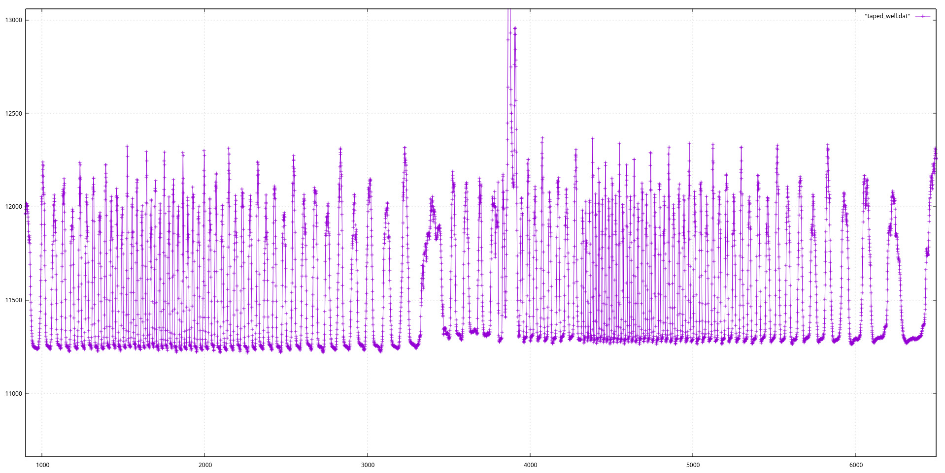
Above: a plot of the radiometer proximity data, taken from the sensor. The first half of the graph shows it spinning in one direction, then it changes at around the 4000 mark on the x-axis to spin in the other direction.
Looking at this (probably somewhat tiny) plot, a pattern is somewhat distinguishable: the troughs of each of the spikes have a different gradient, depending on which direction the radiometer is spinning in - somewhat as we’d expect, from the description we gave above. This reduces the problem to:
- How do we filter out just the bit at the bottom of each spike that we’re interested in from all the rest of the stuff?
- How do we figure out the gradient of said interesting points?
The first bullet point was solved with some hacky application of elementary statistics - we kept a buffer of the last 256 data points received from
the sensor, calculated their mean and standard deviation, and excluded points that were above mean - (stddev / 4) (with the divisor determined
experimentally; 4 seemed to work well enough). This isolated the points to just the few points at the bottom of the trough (or something approximating
that).
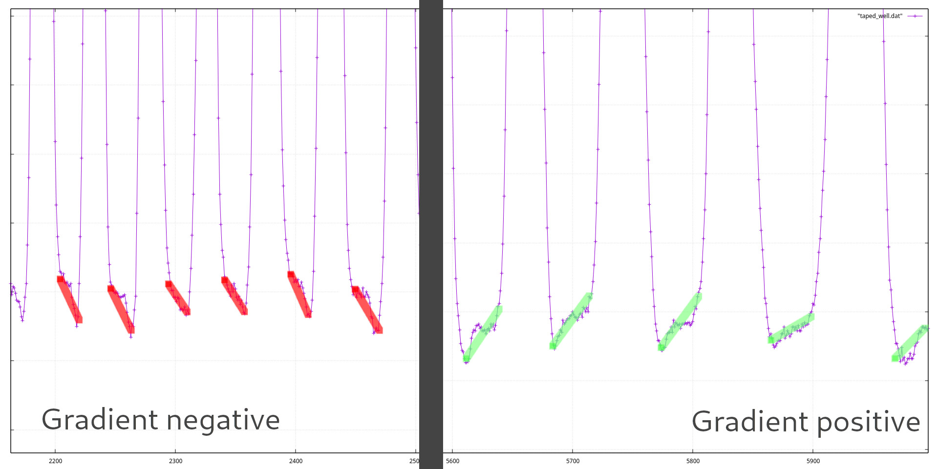
For the second, it was time for…some more elementary stats! As might be obvious, a simple linear regression sufficed, giving us a regression line and its gradient to work with. To prevent data points from being calculated from not enough data, we also prevented regressions from being carried out on data with an insufficiently high range, and rejected results with a low R-value. This finally gave us something vaguely capable of determining the spin direction - and we’d also require 3 or so concordant readings in order to actually come to a judgement, to minimize the chance of random errors. (Remember, a false positive would result in the challenge instantly unlocking, so we wanted to be sure; better to have the cracker wait for 5 seconds or so than to have it randomly unlock out of nowhere!)
Oh, and the issues with the user being able to spray frost (or ethanol) at the sensor were resolved by…judicious use of tape covering the sensor, so nothing could get in at it (!). We also added some tissue paper, so that the ethanol wouldn’t run everywhere and ruin the rest of the safe.
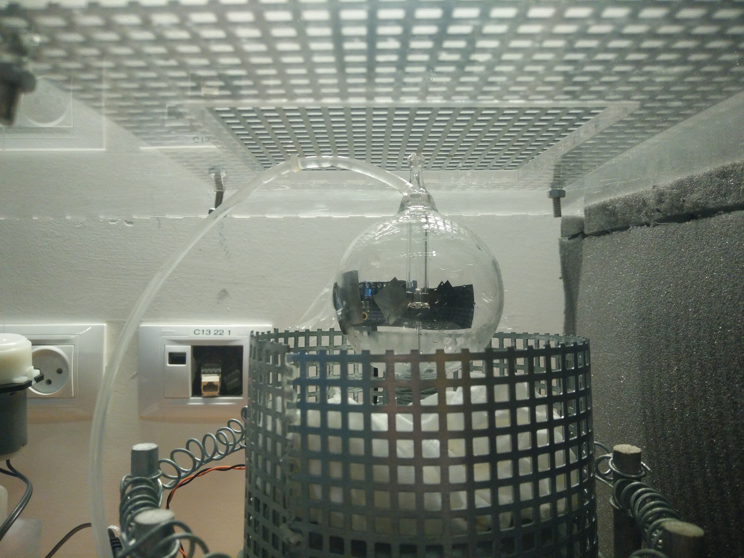
Above: If you look closely, you can just about make out the tape on the other side of the radiometer…
What about the rest of the electronics?
This whole thing was done using STM32F103 microcontrollers, actually - the first revision of the safe used a Blue Pill (see linked blog post for more), while the second revision used the somewhat more reliable Maple Mini. The STM32s were definitely a big plus; they were pretty small, for one, which meant we could stuff the electronics underneath the radiometer (an Arduino Uno would definitely not have fit in!), and their speed (and 32-bit address bus…) made doing calculations like the above regression stuff actually feasible. I used the STM32duino IDE and tooling, primarily because writing drivers (for things like the VCNL4010) didn’t seem like my idea of a fun time (!).
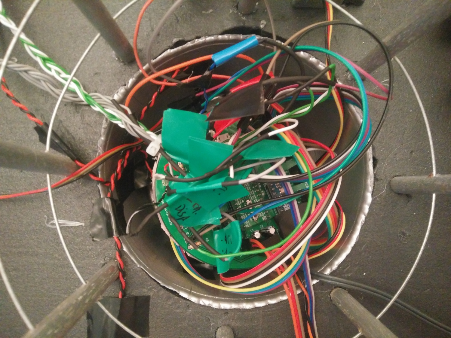
Above: most of the electronics and cabling, stuffed into a well below the radiometer during construction. Connecting all the wires was pretty difficult!
To put things into context, the original revision didn’t use a PCB at all, and instead had tons of flying wires connecting everything on a piece of protoboard; we decided that making a proper PCB for the second revision might be a good idea, so we did:
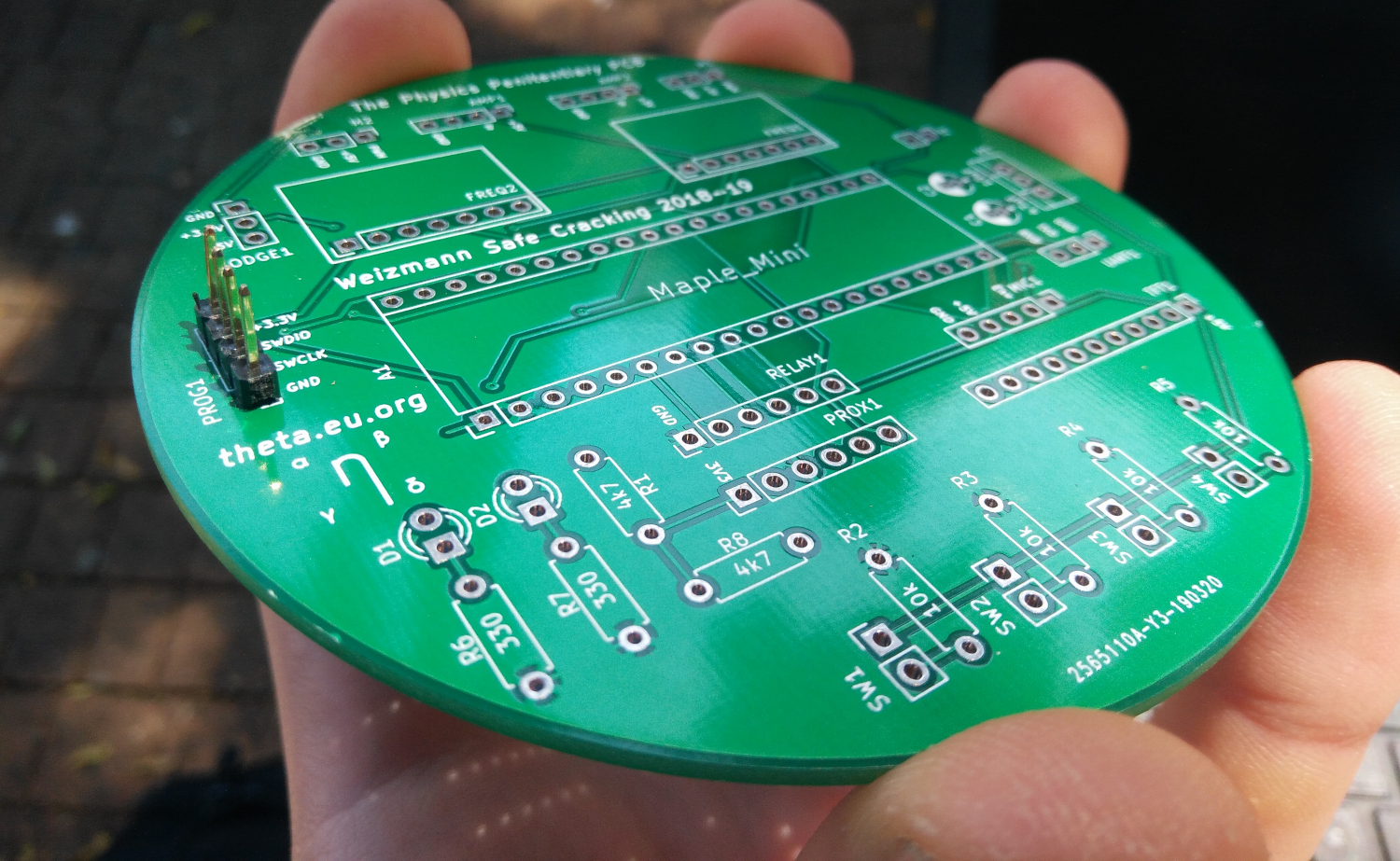
Above: artsy shot of the PCB made for the project, with gratutitous theta.eu.org logo in focus.
In total, the electronics ended up being made up of:
- 1 Maple Mini STM32F103 microcontroller
- 1 VCNL4010 proximity sensor breakout
- 2 AD9833 waveform generator modules, for the frequency challenge
- The first iteration of the safe initially used digital potentiometers (!) to control some hacked up tone generator kits we had lying around; using the AD9833s was definitely a better idea.
- However, finding breakout boards with this IC on them wasn’t an easy task7.
- 1 SparkFun microphone breakout
- 2 amplifiers, to drive the speakers
- 2 servo motors, to control release of the marbles
- 1 Tracopower TSR-2450 voltage regulator, for power input
- I love these modules (for their efficiency); we used one to step down the 9V barrel jack input to a more manageable 5V.
- Some well-placed debug (UART) and programming (SWDIO) headers, to get at the Maple Mini
- Assorted push switches and LEDs for the control panel
- Probably a few passives and other things like that
Source code
As with the Systems CAT, this code is intended to be looked at, rather than used (if you consider yourself patient enough to spend time untangling it, that is!). However, you might find it interesting:
(All rights reserved, no warranty provided, etc.)
Conclusion
Right, that’s probably about enough information for one blog post; it’s been upwards of 2000 words, after all! Hopefully some of it was vaguely informative / interesting; it’s also worth keeping in mind that the actual process of building this thing was significantly more chaotic and panicked than it might seem (c.f. the footnotes below). However, it was definitely a fun thing to build (despite not doing well in the international finals, sadly!)
Do let me know using the comment thing below if you have any more questions about the safe, or feedback; it’s always nice to receive comments!
-
Not my choice of name. ↩
-
The explanations behind the radiometer are apparently still disputed; if you do a search for it, there are a number of conflicting reasons why it behaves like this! ↩
-
If you’re wondering how that actually worked in practice given differences in phase, etc., you’d be onto something. We may or may not have bodged this part a bit to get it to work… ↩
-
It also stopped giving any readings at all if you shone a light at the sensor, which caused some fun issues when it came to cracking the safe. ↩
-
When I say ‘we’, I really mean ‘I’, but it sounds nicer this way. ↩
-
Transporting the safe to Israel was done, of course, on a plane; the sensor positioning was so sensitive that we thought it’d definitely get screwed up by being bumped around… ↩
-
When one of them broke in the week before the international final, trying to hunt around Amazon for another one wasn’t as easy as we would have hoped! ↩
Syndications
This blog post has been syndicated to the following places (feel free to leave a comment there!):